|
|
|
About XT-IDE and XT-CF boards
The XT-IDE board allows you to connect (relatively) modern IDE hard drives or CF memory cards to older IBM PC XT and
compatible computers. It installs on an 8-bit ISA socket and does not require any drivers to be installed. has its own BIOS
on board, which can be configured for specific hardware (from maximum compatibility mode with XT systems to maximum speed on
more modern hardware). The board also has a serial port (optional) for booting the system from a disk image file located on
another computer. The latter is extremely useful when you need to install the system, but there is neither a disk drive with
a system floppy disk, nor a system HDD at hand.
It is recommended to use EEPROM 28C256 as a BIOS (you can also use a less capacious 28C64), then a programmer is not
required to write and update the firmware - this can be done through the DOS utility.
The device supports disks and memory cards of any size (but do not forget about the limitation imposed by the operating
system. For example, MS DOS 6.22 supports disks no larger than 8.4 GB). In total, two disks can be connected to the board.

Firmware and configuration
First you need to download the firmware from the
https://www.xtideuniversalbios.org/
There are various binary options:
| ide_xt.bin |
 |
The assembly uses only processor instructions supported by 8086/8088. This build should work everywhere, including the original IBM PC model 5150. |
| ide_xtp.bin |
 |
Assembly XT+. Similar to the XT assembly, but uses the 80186/80188 instructions (INS and OUTS), which increase data transfer speeds. These instructions are supported by all later x86 including NEC V20/V30. |
| ide_xtl.bin |
 |
Assembly XT large. Assembly of XT with additional modules (see below). Requires 32kb ROM. |
| ide_xtpl.bin |
 |
Assembly XT+ large. Assembly of XT+ with additional modules (see below). Requires 32kb ROM. |
| ide_tiny.bin |
 |
Assembly of XT tiny. Similar to XT assembly, but more compact (fits in 4kb) due to the fact that it uses compressed strings and disables some verification functions. For XT-IDE / XT-CF it makes no sense. |
| ide_at.bin |
 |
Assembly for AT-machines (with 16- and 32-bit bus). Uses 286 instructions. The most complete version, contains all BIOS features. Enables system call interceptions that allow the operating system to do some work while the HDD is busy positioning heads to the desired sector. |
| ide_atl.bin |
 |
AT large assembly. Assembly of AT with additional modules (see below). Requires 32kb ROM. |
| ide_386.bin |
 |
Assembly for 386 and above. Similar to the AT assembly, it includes all possible functionality, but uses some 386 instructions. |
Large builds additionally include the following modules: MODULE_BOOT_MENU, MODULE_8BIT_IDE_ADVANCED and
MODULE_COMPATIBLE_TABLES. Boot menu, allows you to select a disk to boot. Support for DMA and memory mapping, which allows you
to increase the exchange rate by several times through the use of DMA, etc.
But after selecting the BIOS file, you can’t just take and write it down, you must first configure it. This is done with
the xtidecfg.com utility included in the archive.
Run the configurator:
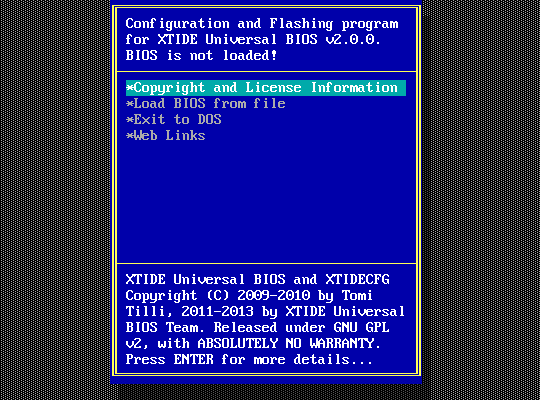
We open the required assembly, after which configuration items and an entry in EEPROM will appear in the menu:
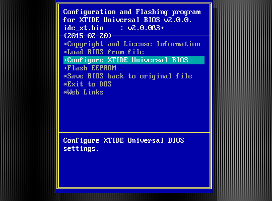
The menu contains the Auto configure command, which will try to determine the device parameters itself.
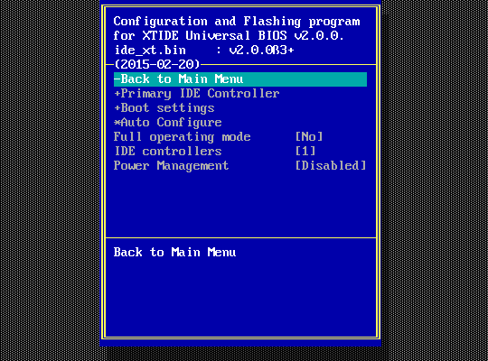
First of all, you need to set the base address so that it matches the address set by the jumpers:
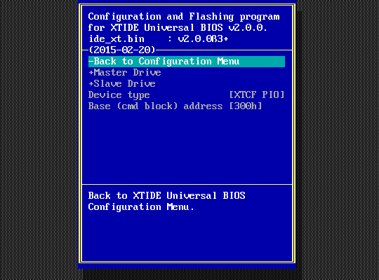
There are also a dozen different options that you can play around with:
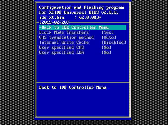
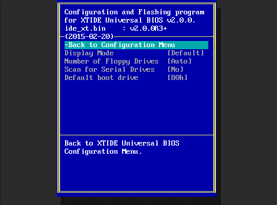
Tooltips for each item are shown at the bottom of the menu. In addition, using the F1 key, you can open a window with a more detailed description of the parameter:
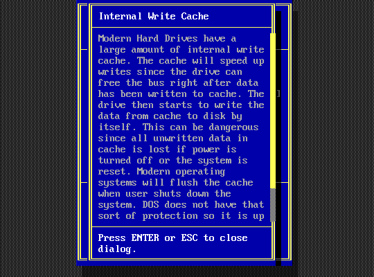
Base (cmd block) address - The base address is the address where the command ports are located. By default,
the primary IDE controller uses port 1F0h and the secondary controller uses port 170h. XTIDE uses port 300h by default.
Control block address - Block of control ports. For IDE controllers, base address + 200h is usually used.
For XTIDE, the block of control registers is located immediately after the block of command registers, i.e., at the address
base + 8h.
Enable interrupt - The IDE controller can use interrupts to signal that data is ready and can be read. This
allows the system to do useful work while the controller is busy. This feature is not very useful in single-tasking MS-DOS,
but using interrupts frees up the bus for other DMA operations. If interrupts are disabled, then polling mode is used, when
the system polls the controller cyclically until it receives a sign of data readiness. In MS-DOS, the polling mode can slightly
increase the speed of work, because. avoids the overhead of interrupts. However, if interrupts are disabled and Block
mode transfers are enabled, then there may be problems with some older HDDs.
IRQ - IRQ channel number. Under MS-DOS, all controllers running the XTIDE Universal BIOS can use the same IRQ
channel. Other operating systems may require each controller to have its own IRQ.
Block mode transfers - The block transfer mode can increase the speed of operation due to the fact that several
sectors will be transferred at once while waiting for a request for the next piece of data. It makes sense to always leave this
option enabled. It should be turned off only if HDDs are used, in which the block transfer mode is poorly implemented.
User specified CHS - In general, the controller can automatically determine the disk geometry. But if the
operating system cannot work with large disks, then you can manually limit the number of sectors for it - Cylinders.
In this case, it is better not to touch the heads and sectors per track parameters - not all
values are valid here.
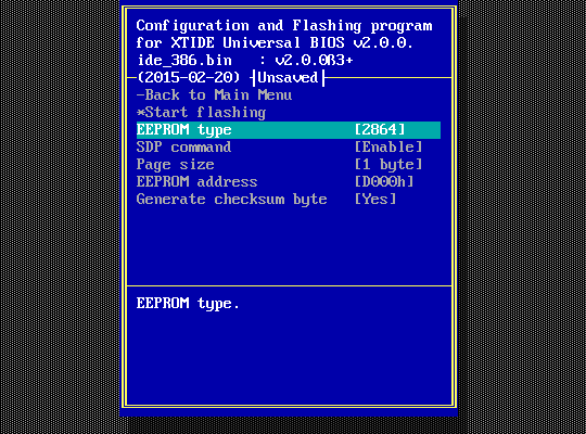
You can update the controller BIOS directly from the configurator utility. The programmer screen looks like this:
XT-CF-Lite V4
XT-CF-Lite is a simplified version of the XT-IDE controller for connecting a CF card instead of an HDD. Its description,
diagram, gerberas and firmware can be downloaded from the author's website.
It uses 8 KB ROM (recommended EPROM 28C64 to be able to update the firmware). This device is quite simple and usually
starts without problems if there are no installation errors. Also on the author's website provides a detailed description
of this device.
In conclusion, a small warning - the boards are 8-bit, and if the backplate is missing, you can insert them into the
ISA slot both correctly and upside down. In the latter case, both devices can fail - sad practice has shown that when
turned on upside down, their ROMs instantly fail. The matter is aggravated by the fact that the IDE controller has an HDD
connector located in front, while the CF controller has a card connector located at the back. And, when you get used to
inserting one card (CF or IDE), then another board can be inserted by inertia in the same way, guided by the connector.
Consider this and be careful!
|


